OCT Scanner
OCT Scanner
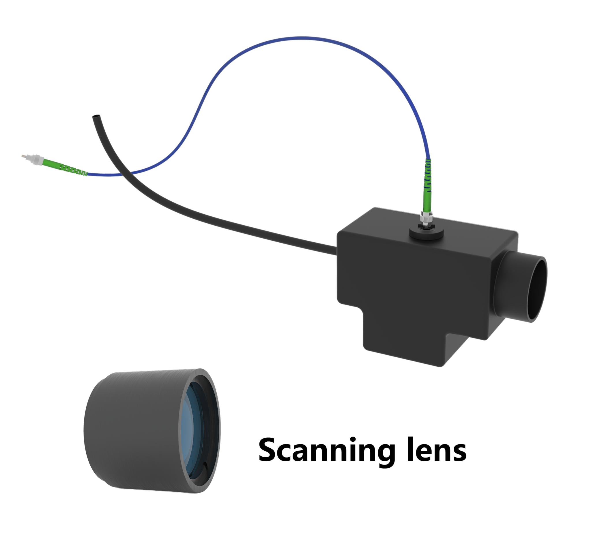
The OCT scanner assembly provided by our company includes: optical fiber collimator, two-dimensional scanning galvanometer, scanning lens group and zoom lens; The scanning head assembly is used in the optical coherence tomography (OCT) laser scanning imaging system.
Four Core Features
Telecentric scanning lenses are crucial for OCT and other laser scanning imaging systems, as they generate a flat imaging plane when the laser beam scans the sample.
Large field of view imaging technology enables imaging of objects within a wide field of view through optical design, image processing and other methods.
Low F-theta distortion produces geometrically corrected images without the need for extensive post image processing.
The combination of the OCT scanning head with self-built microscopes can significantly expand system functionality, with prominent advantages especially in multimodal imaging and cross-scale observation (surface + deep layer) scenarios.
Working Principle
In optical coherence tomography (OCT) and other laser scanning imaging systems, laser beams incident on the back of the aperture (entrance pupil) of a lens are scanned over a certain angular range. Scanning lenses convert the position of the light spot formed on the image plane within the lens field of view. Telecentric scanning lenses are designed to produce a uniform spot size at each scanning position on the imaging plane, a method that enables the formation of high-quality images of the sample. Generally, laser scanning microscopy (LSM) systems are equipped with scanning lenses integrated with tube lenses, resulting in an infinity-corrected optical system. Most OCT systems, however, are designed to use scanning lenses without a scanning tube lens.
When designing an imaging system using an LSM scanning lens in an OCT configuration, it is critical to adjust the design wavelength, parfocal distance, scan distance, entrance pupil, and scan angle specifications to maximize imaging quality. For example, a larger incident beam diameter yields a smaller focused spot size. Nevertheless, the range of the scan angle is reduced with an increase in the beam size due to vignetting and/or increased aberrations.
For single-galvanometer systems, the center of the scanning lens entrance pupil coincides with the pivot point of the galvanometer. When a single galvanometer is used, the scan distance is measured from the mounting surface of the lens to the pivot point of the galvanometer, as illustrated in Figure 1.
If the imaging system utilizes two galvanometers (one for X-direction scanning and one for Y-direction scanning), the entrance pupil is positioned between the two galvanometers, as shown in Figure 2. The scan distance is the sum of the distance from the lens mounting surface to the pivot point of the galvanometer closest to the lens (d1) and the distance from this galvanometer pivot point to the entrance pupil (d2). Minimizing the distance between the two galvanometers is essential, as imaging quality degrades when the entrance pupil is misaligned with the beam control pivot points. This is primarily due to optical path length variations that occur as the beam scans across the sample. Figures 1 and 2 depict imaging systems incorporating a single galvanometer and two galvanometers, respectively.
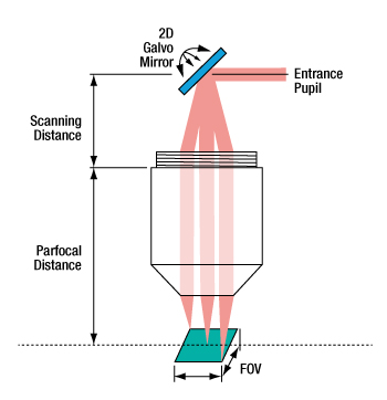
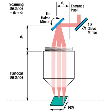
Figure 1
The entrance pupil is located at the pivot point of the galvanometer when a single galvanometer is used.
Figure 2
The entrance pupil is positioned between the two galvanometers when dual galvanometers are used.
Definition of Customizable Acceptable Parameters

Parfocal Distance (PD)
PD is the distance from the mounting plane of the scanning lens to the front focal plane of the scanning lens.

Working Distance (WD or LWD)
WD is defined as the distance between the tip of the scanning lens housing and the front focal plane of the scanning lens.

Entrance Pupil Size (EP)
For a single-galvanometer system, the entrance pupil (EP) is situated at the pivot point of the galvanometer. For a dual-galvanometer system, the EP is positioned between the two galvanometers. The size of the EP is specified as the diameter of the collimated laser beam that maximizes the resolution of the imaging system.

Scan Angle (SA)
The laser beam reflected by the galvanometer is incident on the lens at a specific angle, which is defined as the scan angle measured relative to the optical axis of the lens. The maximum allowable range of the scan angle is listed in the specification sheet.

Field of View (FOV)
FOV refers to the size of the maximum area on the sample where the imaged resolution is equal to or better than the resolution specified for the scanning lens, assuming optimal utilization of the scanning lens in the optical system. In operation, the position of the scanning spot lies within the field of view.

Scan Distance (SD)
SD is the distance between the aperture plane (i.e., the position of the entrance pupil) and the rear side of the objective mounting plane, which is defined as the mounting thread base. For these lenses, the mounting plane is adjacent to the threaded portion or thread plane of the lens. For a dual-galvanometer system, the aperture plane is located midway between the two galvanometers; for a single-galvanometer system, the pivot point of the single galvanometer coincides with the aperture plane.

Depth of View (DOV)
The DOV parameter corresponds to the distance between two parallel planes on either side of the front focal plane, where the beam spot diameter on these planes is √2 times that at the front focal plane. As a general example for OCT, this parameter is useful in the design of optical systems without a tube lens, where the front focal plane also serves as the sample plane. When a tube lens is paired with a scanning lens, the image plane is located between the scanning lens and the tube lens, and the depth of view at the sample is then controlled by the microscope objective.